

In this post we're going to learn the basics of digital sampling and sample rates. Specifically, how a analog to digital converter (ADC) circuit does exactly what it's name implies: measures analog audio signals and converts these measurements to binary numbers. Once we've had our fun mangling those signals in our audio software we need to get them out to our ears and (hopefully) to the ears of others. Since digital data can't push a speaker back and forth we need another circuit called, as you might expect, a digital to analog converter (DAC). Your DAC reads the stored digital samples and uses them to construct a new analog signal. This signal is routed through the outputs of your audio interface to your speakers. Your speakers then vibrate and create sound pressure waves in the air.
We'll also learn that in many ways this all got started with some ideas put forth by a guy named Harry. Harry worked for the phone company 90 years ago.
 |
| I invented this stuff! I want stock options from Apple and Spotify! |
Sorry Harry you've been in the ground for decades. But every time anyone uses any kind of digitally encoded audio your work comes into play. And now it happens millions and millions of times every day. Thank you!
Quick Review
- a sound pressure wave and a analog audio signal are both made up of fluctuating pressure variations
- in a sound wave these are pressure variations in the air
- in an analog audio signal these are electron pressure variations called voltage
- one positive and one negative pressure variation comprise one complete cycle of a wave
- the number of complete cycles that occur in one second are called frequencies and are measured in Hertz (Hz)
- a waveform is a graphic that describes the physical attributes of a wave
Sound Waves, Transducers and Analog Audio
And here we go...
Analog to Digital Conversion (ADC)

Note: As we add more bits to a digital sample an ADC is able to encode the amplitude of a analog signal with greater accuracy. We'll talk more about bit depths in an upcoming post.


Digital samples are discrete measurements of analog amplitudes
Digital to Analog Conversion (DAC)

Note: I've been talking about ADCs and DACs as if they're two separate circuits and they are. But most of you have both circuits (and a lot of other features) built into your audio interface.
Sample Rate
The number of times per second your ADC is measuring, encoding and storing samples is called the sample rate. Sample rates are measured in Hertz (Hz). Again, a single sample is only capable of capturing an analog signal's amplitude at one specific point in time. The sample rate (how many measurements per second) determines how accurately your ADC can capture an analog signals frequency.
On the graphic below I've indicated one complete cycle or wavelength of the analog signal.

See any problem with this? Look at it again.
In this example only the positive side of the analog waveform is being sampled.
This just isn't going to work. At a minimum we need to sample both the positive and the negative phase of each complete cycle of the analog signal.

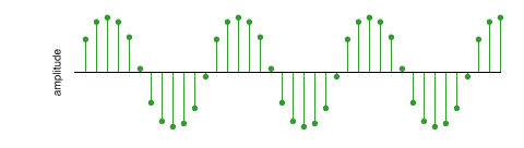
In the example above we've doubled the amount of digital lollipops. Our ADC can now capture both the positive and negative phase of the analog signal.
In order to accurately capture an analog audio signal our digital sample rate must be at least twice the frequency of the analog signal.
Does that make sense? Good. You now understand the basis of the Nyquist Theorem. Harry Nyquist was an electronic engineer who worked for Bell Labs during the first half of the 20th century. His research is the foundation of what would eventually become the process for digitally sampling all kinds of waves. Sometimes big companies with lots of money pay smart people to try to figure stuff out in the hopes of making more money. And sometimes it benefits all of us.
So now we know that in order to accurately sample an analog signal our sample rate has to be at least twice that of the highest frequency of the signal we hope to capture. The range of human hearing in frequency is said to be 20 Hz to 20 kHz. If the highest frequency that we can possibly hear is 20 kHz we might think that we could set the sample rate on our ADC to 40 kHz and be done with it. But..
 |
| good doggie! |
Aliasing


This is called aliasing and we can't have it. Fortunately you don't have to worry about it. The engineers who designed your converter already took care of it.
Anti-aliasing Low Pass Filter
A low pass filter does exactly what it's name implies: it lets low frequencies pass while filtering out the highs. There's a low pass filter built into your ADC just for this purpose: to filter out higher analog frequencies that can cause aliasing.
A filter has a cut-off frequency. This is the point at which it begins to attenuate (reduce) signals. The filter doesn't attenuate infinitely at it's cut-off point; it has a gradual slope. When it reaches the end of the slope all frequencies above that are removed entirely.

Remember, Mr. Nyquist told us that in order to accurately sample an analog audio signal our sample rate must be at least twice as fast as the highest frequency we want to capture.
22.05 kHz * 2 = 44.1 kHz
Ever see that number before?
 |
| The first commercially released audio CD |
Every audio CD that was ever made since the beginning of time in 1982 was encoded at a sample rate of 44.1 kHz
A Few Points Worth Pointing Out
- Occasionally I run across someone who believes that a specific audio software application sounds better than another for recording. This is impossible. When you're recording you're capturing signals from your analog gear (probably mic and mic pre) to your ADC. Your ADC is creating the digital audio samples. The software you're using is irrelevant. Claiming that one DAW sounds better for recording is analogous to claiming that Photoshop it the best program for taking pictures.
- This should also clue you into the fact that regardless of how good DAWs and plugins get at emulating analog gear for mixing your mics, preamps and converters are still going to have a huge effect on the sound of your digital recordings.
- There are a lot of options for working at sample rates higher than 44.1 kHz or "CD quality". 48 kHz is the standard audio sample rate for the film/video industry. Other than that the topic of higher sample rates can be highly contentious and has been debated fervently for quite awhile now. It's beyond the scope of this article to get into it but I suggest you check it out on your own, you're eventually going to start asking about it anyway. Here's a few links to get you started:
Finally...
A Little Bit on Bit Depth
All those lollipop graphics I showed you earlier are really nice for illustrating sample rates. However the truth of the matter is that those dots on the lollipop tops are very often not going to precisely coincide with the amplitudes of your analog signals. Don't worry about it, this was all taken into consideration and compensated for a long time ago. But next time we'll have to talk about bit depths and quantization.
In the meantime if you're not too sure what a "bit" is you can find out here:
Bits and Binary 101 = 5
Karl Wenninger is an audio engineer, synthesist/sound designer, composer, guitarist and DIY audio electronics enthusiast. As an adjunct professor he has taught Pro Tools at The New School for Jazz and Contemporary Music, Computer Music at York College and Audio Post-Production for the Media Arts Program at NJCU. He was an program administrator and associate professor at the former Digital Media Arts program at Touro College in New York City for over a decade.
Great Read!
ReplyDelete